So after driving my Xterra around for 6 years with cracked exhaust manifolds I decided to finally install the AC headers I purchased a year and a half ago to remedy the problem. I did not see a DIY for headers so I thought I would post one.
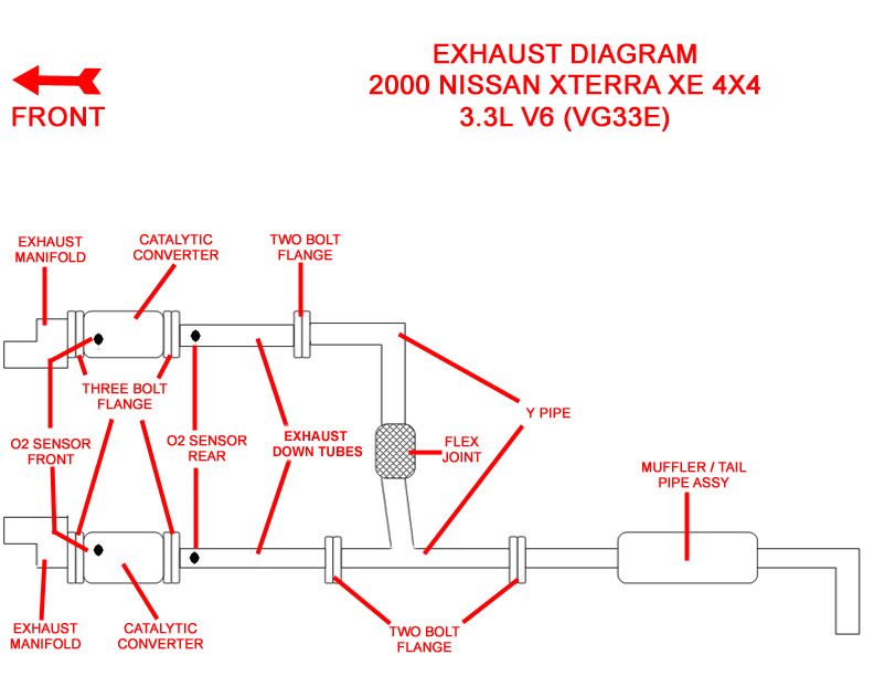
This DIY shows the process of installing AC headers and CEL’s on a 2000 Xterra XE 4x4 3.3l V6 with a 2” body lift utilizing the OEM down tubes. I can't even imagine how difficult this mod would be on a vehicle without the body lift. The extra 2” gap created by the body lift makes all the difference in the world, so much so that if I wanted headers I would first install a body lift just to make it easier.
I am sure there are variations for later model year 1st Gen’s but it should give the basic outline of the install. The AC header is a long tube header and will eliminate the cats. In order to keep the cats you will have to fabricate new down tubes and install Hi Flow aftermarket cats and extend the rear O2 sensor leads.
PARTS NEEDED
1 Set of AC Headers
2 CEL (Check Engine Light Eliminator)
2 EX Manifold Gaskets
12 Short EX Manifold Studs (5 will absolutely be needed but error on the safe side and get 12)
3 EX Flange Gaskets (2 Bolt)
2 Crush Gaskets (OEM gasket between cats and down tubes)
1 EGR Plug 14052-21R00 Nissan part number (Only needed if you can not get the old one loose)
SUPPLIES NEEDED
PB Nut Blaster
Anti-Seize High Temp
High Temp Loctite
Scotch Brite Green Pad
2” to 4” Zip Ties
TOOLS NEEDED
Floor Jack
Jack Stands
Wheel Removal Tools
Short and Long Handled 3/8 Ratchet
Assortment of 3/8 Extensions
3/8 Deep Sockets 14mm, 17mm
3/8 Standard Sockets 10mm, 12mm, 14mm, 17mm
3/8 Swivel Drive
3/8 Torque Wrench
Short 1/4 Ratchet
4” 1/4 Extension
1/4 Standard Sockets 8mm, 10mm
Short Wrenches 14mm, 17mm
Long Wrenches 22mm
Side Cutters
Sawzall or Right Angle Grinder
PREPERATION
Start off by removing the heat shields on the EX manifolds and getting out the PB Blaster and soaking down the following points.
EX manifold studs and nuts (12)
Studs and nuts that attach the cats to the EX manifolds and to the down tubes (12)
The bolts that hold the Y pipe flanges together (6)
Y pipe mounting bolt located just to the passenger side of the flex pipe (1)
Large plug located on the top of the driver’s side ex manifold
I suggest you do this for at least a week to aid in ease of removal. Make sure to spray both sides of the cats and Y pipe mounting hardware.
![Image]()
GETTING STARTED
Chock the rear wheels and set the parking brake.
Disconnect the negative cable from the battery.
Label the four O2 connectors located on the passenger side valve cover. A Sharpie works great and make sure to label both sides of the connector.
![Image]()
Gently pull the connector towards the front of the vehicle to remove the O2 connectors from there mounting tabs.
Disconnect the O2 sensors from the wiring harness and begin to trace them towards the sensors cutting the wire ties that attach them to the mounting brackets as you go. You are doing this to avoid damaging the wires from the twisting force of removing the O2 sensors from the down tubes and cats.
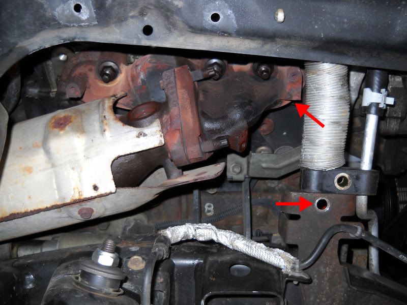
Starting just in front of the muffler remove the 6 bolts and nuts located at the 3 flanges on the Y pipe using a 14mm wrench and socket. Next remove the 1 mounting bolt located on the passenger side of the flex joint using a 14mm deep socket and move the Y pipe towards the rear of the vehicle. You are doing this to allow room to easily remove the down tubes.
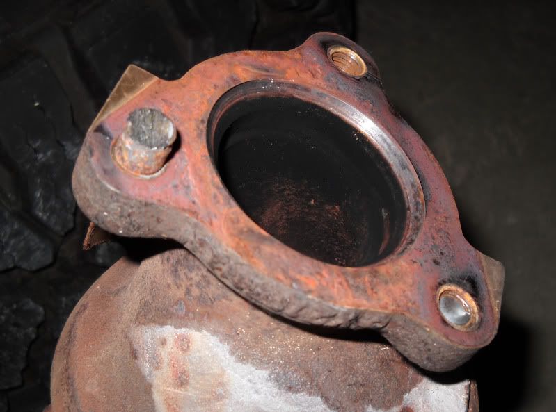
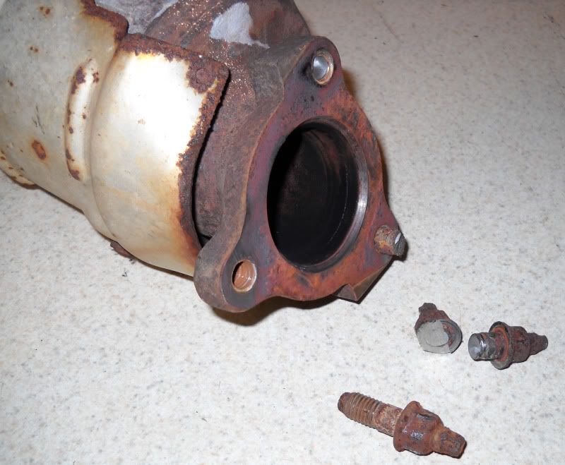
Remove the 6 nuts that attach the down tubes to the cats using a 14mm deep socket. On mine 2 of the studs snapped off and one would not budge so a sawzall had to be used to cut it off. With the down tubes free carefully remove them taking care not to damage the O2 sensors, leads, or connectors. Once the tubes have been removed set them aside.
![Image]()
![Image]()
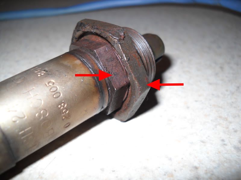
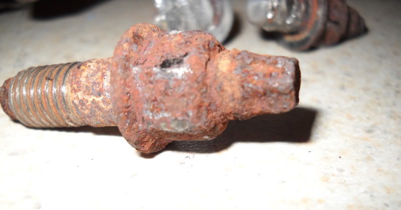
There is not enough PB Blaster on the face of the planet to get this nut loose.
![Image]()
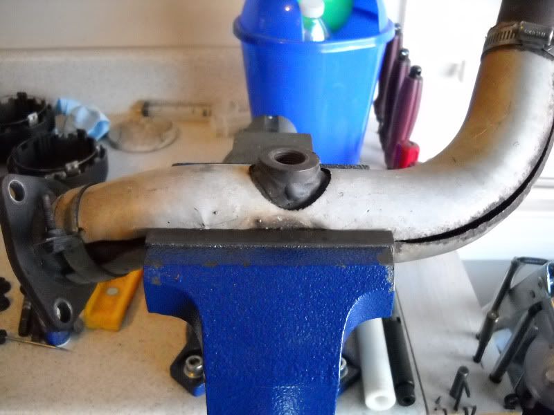
Secure the down tubes so they cannot turn, a vice works great, and using a 22mm wrench remove the O2 sensors from the down tubes. Once removed set the sensors someplace safe to avoid damage.
![Image]()
Next using a floor jack lift the front of the vehicle and remove the front tires then place jack stands under the vehicle to support it. With the tires removed you can now begin removing the manifolds and cats. You can start on either side but the drivers side will be the toughest.
This DIY shows the process of installing AC headers and CEL’s on a 2000 Xterra XE 4x4 3.3l V6 with a 2” body lift utilizing the OEM down tubes. I can't even imagine how difficult this mod would be on a vehicle without the body lift. The extra 2” gap created by the body lift makes all the difference in the world, so much so that if I wanted headers I would first install a body lift just to make it easier.
I am sure there are variations for later model year 1st Gen’s but it should give the basic outline of the install. The AC header is a long tube header and will eliminate the cats. In order to keep the cats you will have to fabricate new down tubes and install Hi Flow aftermarket cats and extend the rear O2 sensor leads.
PARTS NEEDED
1 Set of AC Headers
2 CEL (Check Engine Light Eliminator)
2 EX Manifold Gaskets
12 Short EX Manifold Studs (5 will absolutely be needed but error on the safe side and get 12)
3 EX Flange Gaskets (2 Bolt)
2 Crush Gaskets (OEM gasket between cats and down tubes)
1 EGR Plug 14052-21R00 Nissan part number (Only needed if you can not get the old one loose)
SUPPLIES NEEDED
PB Nut Blaster
Anti-Seize High Temp
High Temp Loctite
Scotch Brite Green Pad
2” to 4” Zip Ties
TOOLS NEEDED
Floor Jack
Jack Stands
Wheel Removal Tools
Short and Long Handled 3/8 Ratchet
Assortment of 3/8 Extensions
3/8 Deep Sockets 14mm, 17mm
3/8 Standard Sockets 10mm, 12mm, 14mm, 17mm
3/8 Swivel Drive
3/8 Torque Wrench
Short 1/4 Ratchet
4” 1/4 Extension
1/4 Standard Sockets 8mm, 10mm
Short Wrenches 14mm, 17mm
Long Wrenches 22mm
Side Cutters
Sawzall or Right Angle Grinder
PREPERATION
Start off by removing the heat shields on the EX manifolds and getting out the PB Blaster and soaking down the following points.
EX manifold studs and nuts (12)
Studs and nuts that attach the cats to the EX manifolds and to the down tubes (12)
The bolts that hold the Y pipe flanges together (6)
Y pipe mounting bolt located just to the passenger side of the flex pipe (1)
Large plug located on the top of the driver’s side ex manifold
I suggest you do this for at least a week to aid in ease of removal. Make sure to spray both sides of the cats and Y pipe mounting hardware.
GETTING STARTED
Chock the rear wheels and set the parking brake.
Disconnect the negative cable from the battery.
Label the four O2 connectors located on the passenger side valve cover. A Sharpie works great and make sure to label both sides of the connector.
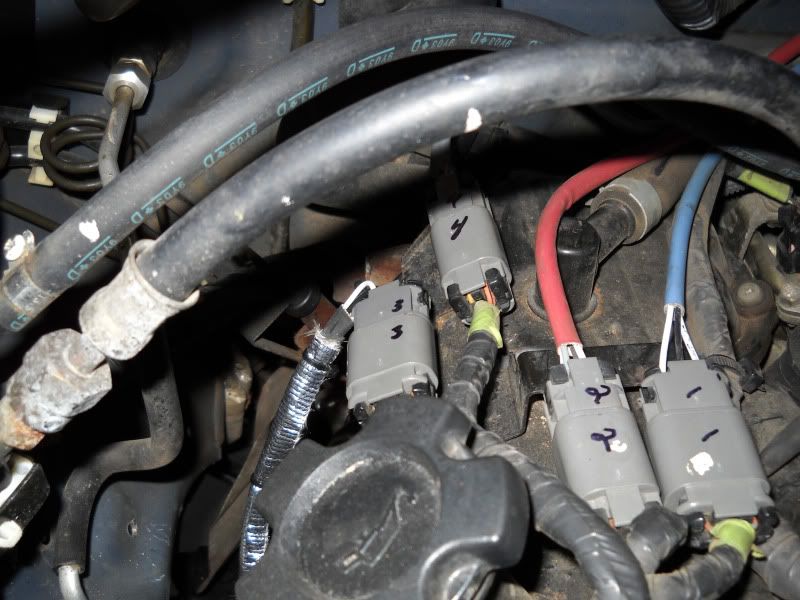
Gently pull the connector towards the front of the vehicle to remove the O2 connectors from there mounting tabs.
Disconnect the O2 sensors from the wiring harness and begin to trace them towards the sensors cutting the wire ties that attach them to the mounting brackets as you go. You are doing this to avoid damaging the wires from the twisting force of removing the O2 sensors from the down tubes and cats.
Starting just in front of the muffler remove the 6 bolts and nuts located at the 3 flanges on the Y pipe using a 14mm wrench and socket. Next remove the 1 mounting bolt located on the passenger side of the flex joint using a 14mm deep socket and move the Y pipe towards the rear of the vehicle. You are doing this to allow room to easily remove the down tubes.
Remove the 6 nuts that attach the down tubes to the cats using a 14mm deep socket. On mine 2 of the studs snapped off and one would not budge so a sawzall had to be used to cut it off. With the down tubes free carefully remove them taking care not to damage the O2 sensors, leads, or connectors. Once the tubes have been removed set them aside.
There is not enough PB Blaster on the face of the planet to get this nut loose.
Secure the down tubes so they cannot turn, a vice works great, and using a 22mm wrench remove the O2 sensors from the down tubes. Once removed set the sensors someplace safe to avoid damage.
Next using a floor jack lift the front of the vehicle and remove the front tires then place jack stands under the vehicle to support it. With the tires removed you can now begin removing the manifolds and cats. You can start on either side but the drivers side will be the toughest.