This thread is still a work in progress, but I just added lock/unlock info to this post, and door open/closed trigger info in a reply below.
It's a Viper 5901.
Original post here :
I found this site useful when installing
I decided to place the brain below the storage pocket in front of the shifters. There's barely enough room, but with enough cramming, it fits.
There were many unused wires coming off the Viper harness. I bundled them up about 6" away from the connector and ziptied them together.
Pull the stereo out, and the drivers side panel in front of your knees, and the steering column cover. You should be able to do this all with a #2 and #3 philips. I also took off both the kick panels and removed the glove compartment, but don't know how necessary those really were.
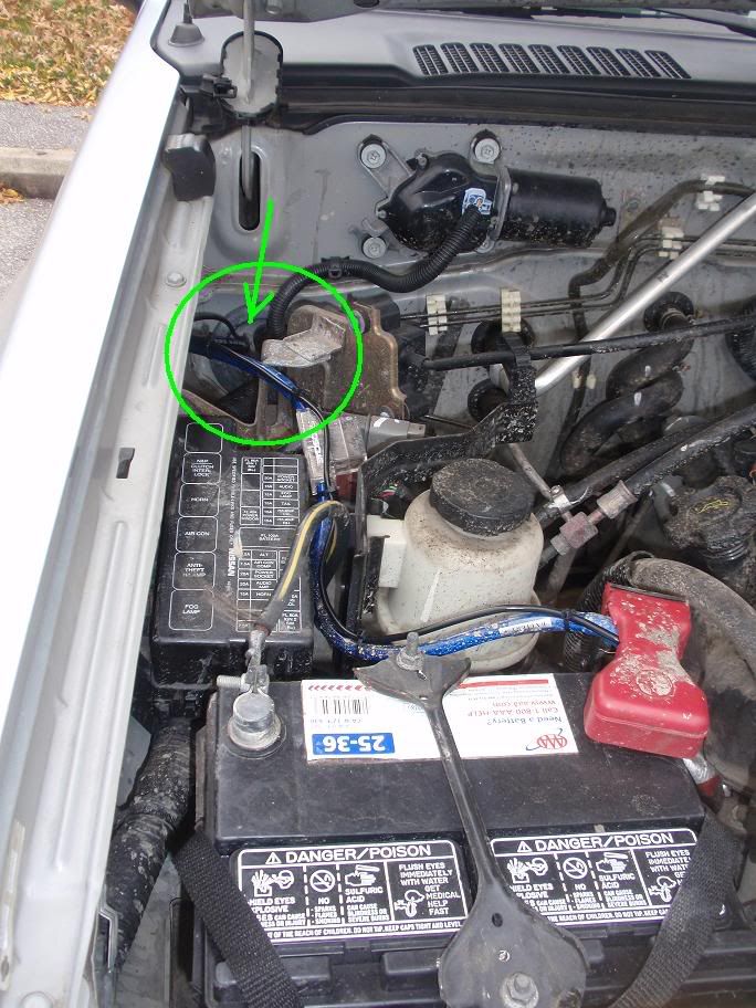
For power, use an 8-9 gauge wire directly from the battery, fused close to the battery (50A) like for a speaker amp. Ran it through 3-4" grommet passenger side footwell, to a power distro block to the 3 power wires for the rem start. See pic at bottom. Arrow points to the grommet I poked with a box knife to make a slit then shoved the power wire through with needle nose pliers. Stuff it until it stops, then go inside the cab - I'm 2 for 2 on being able to reach wires when I used this method, but I suppose there's a chance it will get hung up on something and not come down from where the grommet is.
For ground, I used a bolt that holds the t-case shifter down.
At steering column, hooked both ignition and starter wires together with the output from the remote starter. I think there are two of each to carry twice the current without increasing the wire size of a single wire.
Quick-tap into the brake wire above pedal.
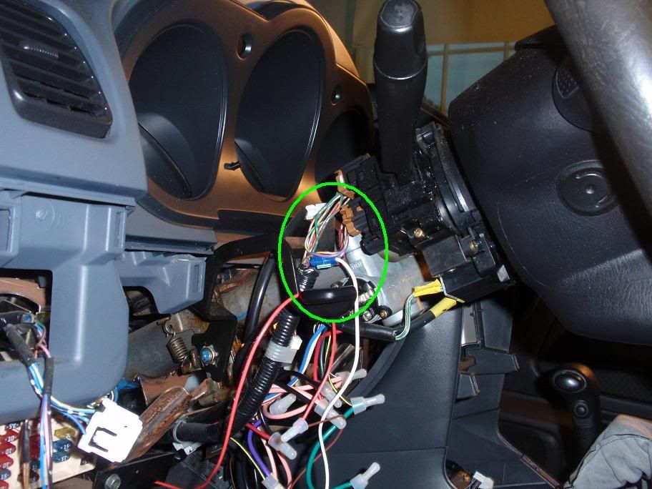
Parking light output connected to wire under steering column cover. See pic for the area I tapped into.
Hood switch - Use wire 6 at the SECU. Gives a ground when hood opened.
Neutral start switch - hook to a ground.
Remote start enable switch - connect and run to footwell but secure switch just behind the edge of the panel so you have to reach behind to flip it.
Pulled the a-pillar off and stuck the antenna right above the rear view mirror with the wire going right into the headliner. Ran wire down a-pillar through the brackets Nissan nicely put there for me, and tucked into edge of dashboard.
I didn't use the siren because I was only concerned with the remote start. I hooked it up temporarily for programming options because it chirps a certain number of times to indicate which menu you're in.
Programming - you have to set it to "automatic transmission" mode; the default is manual. (if you have an auto, of course.)
See my reply below for how to hook up the door open/closed signal.
For lock, give a ground to SECU wire 10 (Yel/Red).
For unlock, give a ground to SECU wire 11 (Yel). May require a double-pulse.
Power wire grommet:
![Image]()
Wire for park lights is in here, where the blue quick-tap is:
![Image]()
It's a Viper 5901.
Original post here :
I found this site useful when installing
I decided to place the brain below the storage pocket in front of the shifters. There's barely enough room, but with enough cramming, it fits.
There were many unused wires coming off the Viper harness. I bundled them up about 6" away from the connector and ziptied them together.
Pull the stereo out, and the drivers side panel in front of your knees, and the steering column cover. You should be able to do this all with a #2 and #3 philips. I also took off both the kick panels and removed the glove compartment, but don't know how necessary those really were.
For power, use an 8-9 gauge wire directly from the battery, fused close to the battery (50A) like for a speaker amp. Ran it through 3-4" grommet passenger side footwell, to a power distro block to the 3 power wires for the rem start. See pic at bottom. Arrow points to the grommet I poked with a box knife to make a slit then shoved the power wire through with needle nose pliers. Stuff it until it stops, then go inside the cab - I'm 2 for 2 on being able to reach wires when I used this method, but I suppose there's a chance it will get hung up on something and not come down from where the grommet is.
For ground, I used a bolt that holds the t-case shifter down.
At steering column, hooked both ignition and starter wires together with the output from the remote starter. I think there are two of each to carry twice the current without increasing the wire size of a single wire.
Quick-tap into the brake wire above pedal.
Parking light output connected to wire under steering column cover. See pic for the area I tapped into.
Hood switch - Use wire 6 at the SECU. Gives a ground when hood opened.
Neutral start switch - hook to a ground.
Remote start enable switch - connect and run to footwell but secure switch just behind the edge of the panel so you have to reach behind to flip it.
Pulled the a-pillar off and stuck the antenna right above the rear view mirror with the wire going right into the headliner. Ran wire down a-pillar through the brackets Nissan nicely put there for me, and tucked into edge of dashboard.
I didn't use the siren because I was only concerned with the remote start. I hooked it up temporarily for programming options because it chirps a certain number of times to indicate which menu you're in.
Programming - you have to set it to "automatic transmission" mode; the default is manual. (if you have an auto, of course.)
See my reply below for how to hook up the door open/closed signal.
For lock, give a ground to SECU wire 10 (Yel/Red).
For unlock, give a ground to SECU wire 11 (Yel). May require a double-pulse.
Power wire grommet:
Wire for park lights is in here, where the blue quick-tap is:

")